
LYFOOCRANE Engineered Cable-Handling Equipment
Clutch-Equipped Industrial Winch for Cable Pulling and Controlled Rope Payout
A configurable pulling system that combines variable-speed drive control with a clutch-decoupled drum. It is designed for applications where operators need powered cable traction during the working cycle and rapid rope payout during setup.


Powered Pulling When You Need It—Faster Rope Deployment Between Cycles
Conventional winches require the motor and gearbox to rotate whenever rope is paid out. In this design, an electromagnetic clutch separates the drum from the drive train for a free-spooling mode. The operator can deploy the rope more quickly, then re-engage the drive for controlled pulling. A grooved drum and spring-loaded pressure roller help keep the rope seated and organized through both operating modes.
Clutch-Decoupled Drum
Separates the drum from the geared drive to support rapid rope payout during setup.
Variable-Speed Pulling
Frequency-controlled operation provides adjustable speed with smoother acceleration and stopping.
Guided Rope Winding
Drum grooves guide each wrap while the pressure roller helps reduce loose coils and rope jump.
Application-Based Build
Capacity, speed, rope storage, controls and mounting are selected around the actual pulling task.
Four Functions in One Cable-Handling System
01 — Pull
Brake Motor Drive
Provides powered traction and secure stopping through a variable-frequency braking drive.
02 — Transmit
Hardened Gear Reducer
Converts motor output into usable drum torque with stable, efficient power transmission.
03 — Release
Electromagnetic Clutch
Engages the powered drive for pulling and disengages it for controlled free-spooling.
04 — Manage
Grooved Drum and Presser
Maintains rope contact at the drum and promotes a more consistent winding pattern.
General Configuration Range
| Design Item | Available Configuration |
|---|---|
| Pulling / Lifting Capacity | 100 to 8,000 kg; engineered to suit the operating condition |
| Power Supply | 220–380 V AC; single-phase or three-phase versions available |
| Drive Control | Variable-frequency brake motor for adjustable-speed operation |
| Transmission | Industrial hardened-gear reduction drive |
| Drum Disconnection | Electromagnetic clutch for drive-decoupled rope payout |
| Rope Management | Grooved drum with spring-loaded rope pressure roller |
| Standard Enclosure Protection | IP55; higher protection levels available when specified |
| Configurable Elements | Rope speed, rope diameter and length, control method, mounting frame and operating logic |
The capacity range covers multiple engineered versions. Final permissible pull, suspended load, drum capacity and duty cycle must be confirmed for each project.
500 kg Reference Configuration
The following values describe one example unit and should not be applied to other capacities without engineering confirmation.
| Rated Capacity | Wire Rope | Drum Speed | Motor Power | Rope Speed |
|---|---|---|---|---|
| 500 kg | 12 mm | 15 rpm | 3 kW | 14 m/min |
| Model | Length (A) | Width (B) | Height (C) |
|---|---|---|---|
| 500KG | 794 mm | 938 mm | 475 mm |
Reference Dimensions
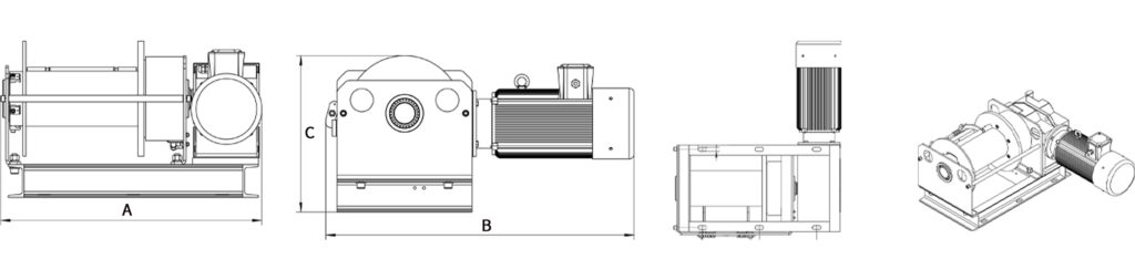
Drawing applies to the reference unit. Dimensions may change with rope capacity, transmission ratio, motor size and mounting arrangement.
Typical Operating Sequence
The clutch changes how the drum connects to the drive train. Interlocks and the exact operating sequence should be defined for the complete machine or production line.
Important: Free-spooling must not be used to release an uncontrolled suspended load. Operating and safety procedures must match the final machine design, applicable regulations and site risk assessment.

Applications That Benefit from Rapid Rope Payout
Automated Production Lines
Pull workpieces, transfer materials or reposition equipment between manufacturing stations.
Test and Research Equipment
Deploy and retrieve cables for test rigs, experimental platforms and engineering systems.
Machine Building
Control component movement and cable-actuated positioning on custom industrial machinery.
Warehouse Handling
Provide controlled traction for bins, carts and light material-handling mechanisms.
Stage and Venue Systems
Adjust non-passenger lighting, audio or display equipment where flexible cable handling is required.
Long-Distance Cable Pulling
Deploy rope quickly before a controlled powered pull across an extended working distance.
Engineering Options
Information Required for Winch Selection
To size the motor, reducer, clutch, drum and wire rope correctly, please include the following details with your inquiry:
Project Engineering FAQ
What is the purpose of the clutch?
The clutch connects the drum to the powered drive for traction and separates the two for faster rope payout. Its engagement logic must be interlocked with the machine’s operating and safety controls.
Can the free-spooling speed be controlled?
Resistance and payout behavior can be engineered within the mechanical design, but free-spooling is not the same as powered closed-loop speed control. Required payout behavior should be defined during application review.
Can it connect to an existing PLC?
Yes. Drive commands, clutch status, interlocks and fault signals can be configured after the PLC model, required I/O and communication method are confirmed.
Is the pressure roller adjustable?
The spring force and roller arrangement can be matched to the selected rope diameter and construction. Additional rope guidance may be added for demanding spooling conditions.
Can the winch be used for lifting?
A lifting version is possible only when the complete system is specifically engineered, rated and equipped for suspended-load service. A pulling configuration must not automatically be treated as a lifting winch.
Application Review Available
Build the Winch Around Your Cable-Pulling Process
Send LYFOOCRANE your required line pull, rope travel, speed, duty cycle, installation drawing and control requirements. We will review the application and prepare a project-specific configuration.
Images and reference specifications are provided for preliminary selection. Final ratings, dimensions, control logic and safety provisions are subject to engineering confirmation.