
LYFOOCRANE Automation-Ready Lifting Systems
PLC-Integrated Servo Winch for Industrial Machine Builders
A configurable motion-control winch for OEM equipment, automated production lines and space-constrained installations. Servo drive technology, programmable controls and a shaft-connected drum layout give engineers greater freedom to coordinate lifting or pulling with the rest of the machine.
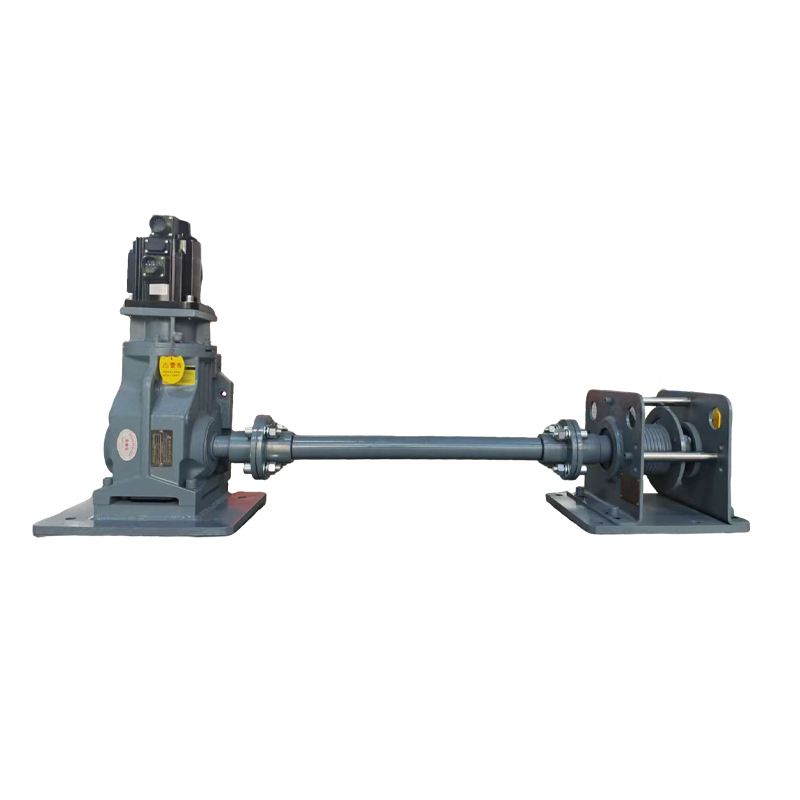
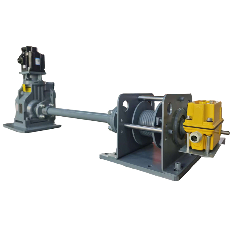
A Winch Designed as Part of the Machine
This system is intended for projects where a winch must communicate with other equipment rather than operate as an isolated device. The servo drive manages programmed motion, while the PLC exchanges commands, status signals and interlocks with the host machine. A separate drive shaft between the gearbox and drum allows the drive package and rope-handling section to be positioned around structural or space limitations.
Programmable Motion
Configure speed, acceleration, deceleration, travel and operating sequences around the process.
PLC Connectivity
Exchange machine commands, ready states, faults, limits and interlock signals.
Flexible Equipment Layout
A shaft-driven drum can be located away from the motor and gearbox when the installation demands it.
Managed Rope Winding
Dual grooved drums support a more orderly rope path across the selected travel.
Industrial Integration Architecture
Motion Layer
Servo Motor and Drive
Provides adjustable motor speed and responsive torque control for the approved motion profile.
Control Layer
PLC and Machine I/O
Coordinates the winch with sensors, process equipment, operator controls and safety functions.
Transmission Layer
Hardened-Gear Reducer
Converts motor output into usable drum torque for the selected load and speed.
Mechanical Layer
Remote Shaft and Drum
Separates the rope-handling location from the main drive package to suit complex machine layouts.
Travel Layer
Adjustable Limit Points
A four-point limit arrangement provides configurable travel references and over-travel inputs.
Operator Layer
Local or Centralized Control
Use a pendant, customer HMI, remote commands or the main equipment control system.
General Technical Range
| Design Item | Available Configuration |
|---|---|
| Nominal Capacity Range | 250 to 8,000 kg; final rating determined by application review |
| Power Supply | 220–380 V AC with single-phase or three-phase versions |
| Primary Drive | Servo motor and programmable drive |
| Gear Reduction | K-series hardened-gear reducer or project-specific equivalent |
| Drum Configuration | Dual grooved drums for managed rope winding |
| Drive-Shaft Layout | Custom shaft length and support arrangement for separated drive and drum locations |
| Travel Limiting | Four-point adjustable limit-switch arrangement |
| Control Methods | Pendant station, remote commands, HMI or PLC integration |
| Base Enclosure Protection | IP55; higher environmental protection available when specified |
| Project Variables | Rope speed, rope length and diameter, feedback devices, PLC logic, mounting and shaft geometry |
Positioning performance is application-dependent. Accuracy must be confirmed from the selected feedback device, rope-layer geometry, load behavior, mechanical compliance and control architecture.
600 kg Reference Configuration
The values below describe one example unit. Other capacities require separate drive, drum, rope and structural verification.
| Rated Capacity | Wire Rope Diameter | Drum Speed | Motor Power | Nominal Rope Speed |
|---|---|---|---|---|
| 600 kg | 6 mm | 13 rpm | 0.85 kW | 4.8 m/min |
| Model | Length (A) | Width (B) | Height (C) |
|---|---|---|---|
| 600KG | 1,260 mm | 280 mm | 560 mm |
Reference Dimensions
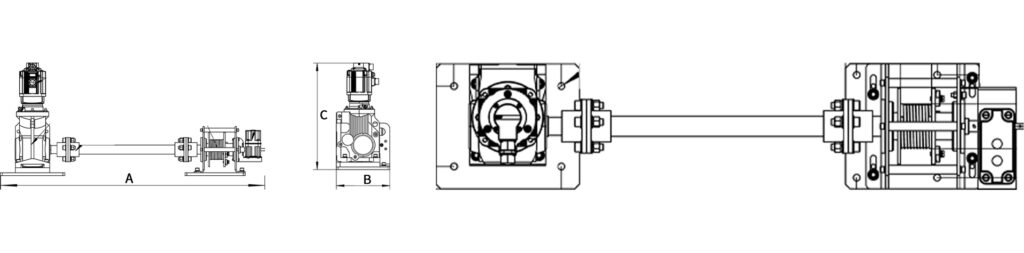
Drawing applies to the reference unit. Final dimensions and shaft supports depend on capacity, rope storage and installation geometry.
PLC Integration Scope
The winch control package can be supplied as a functional subsystem or adapted to the customer’s automation platform. Interface details are finalized from the host machine’s electrical standards and sequence of operation.
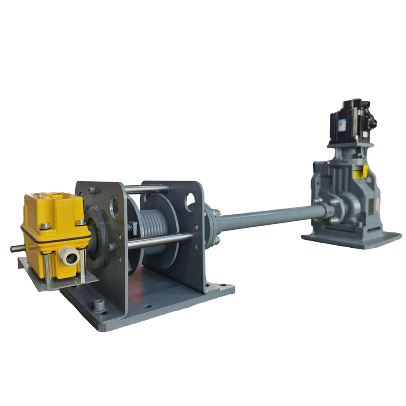
Integration Applications
Production-Line Machinery
Add controlled vertical or pulling motion to automated work cells and assembly equipment.
Machine Tools and Fixtures
Position molds, tooling or workpieces where smooth speed changes and repeatable travel are required.
Automated Storage Systems
Move bins, platforms or handling mechanisms under centralized warehouse controls.
Test and Inspection Equipment
Provide programmable movement for test fixtures, measurement platforms and cyclic test rigs.
Parking and Access Equipment
Integrate a traction subsystem into specialized mechanical platforms after application review.
Restricted-Space Installations
Use the separated drive and drum arrangement when structural obstacles limit conventional layouts.
Engineering Options
Safety Must Be Engineered at System Level
Limit switches are part of the motion-control architecture but should not be treated as the complete safety system. The machine builder remains responsible for the risk assessment and for specifying suitable brakes, overload protection, emergency stopping, guarding, safe control functions and structural load paths for the final installation.
Information Needed for Engineering
System Integrator FAQ
Can the winch connect to our existing PLC?
Yes, after the control platform and interface requirements are reviewed. Provide the PLC model, protocol, electrical standard, I/O list and sequence of operation.
What positioning accuracy can be achieved?
There is no universal value. Accuracy depends on the feedback location, rope layers, drum diameter, load movement, structural compliance and control tuning. The target should be stated in the project specification and verified during commissioning.
How long can the remote drive shaft be?
The allowable length depends on torque, speed, shaft diameter, alignment and bearing support. Long shafts may require intermediate bearings, guards and torsional analysis.
Can the system be supplied as an OEM subsystem?
Yes. Mechanical interfaces, electrical panels, control boundaries and documentation can be defined around the host equipment manufacturer’s scope.
Is the listed 600 kg model suitable for every 600 kg application?
Not necessarily. Lift height, reeving, duty cycle, acceleration, drum layers and safety factors can change component selection even when the nominal load is the same.
OEM and System-Integration Support
Add Controlled Winch Motion to Your Machine
Send LYFOOCRANE your load cycle, installation drawing, shaft distance, positioning target and PLC requirements. We will review the application and prepare an integration-ready servo winch proposal.
Images and reference specifications are provided for preliminary selection. Final ratings, dimensions, controls and safety provisions are subject to project engineering and commissioning requirements.