
LYFOOCRANE Instrumented Motion Systems
Instrumented Servo Winch for Precision Testing and Research Systems
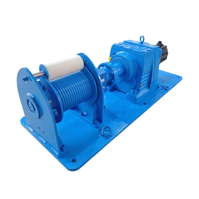
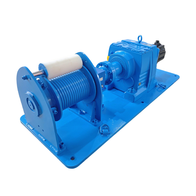
A programmable lifting and traction platform combining servo motion control, real-time torque measurement and guided wire-rope winding. Developed for test rigs, research equipment and advanced machine integration where both movement and load data matter.
Motion Control with Measured Load Feedback
The system is built for applications that need more information than a conventional winch can provide. Servo control manages the commanded movement, while an integrated torque sensor measures transmission load for monitoring, data collection and configurable alarm logic. PLC programming coordinates speed profiles, travel limits, interlocks and communication with the surrounding test or production equipment.
Servo-Controlled Movement
Program operating speed, acceleration, deceleration, direction and target positions.
Torque-Based Monitoring
Observe transmission load and use calibrated thresholds within the machine-control strategy.
PLC and Data Integration
Exchange commands, limits, alarms and process values with a test bench or host machine.
Controlled Rope Spooling
Grooved drums and nylon pressure rollers help guide the rope and reduce displaced wraps.
Core System Elements
Drive
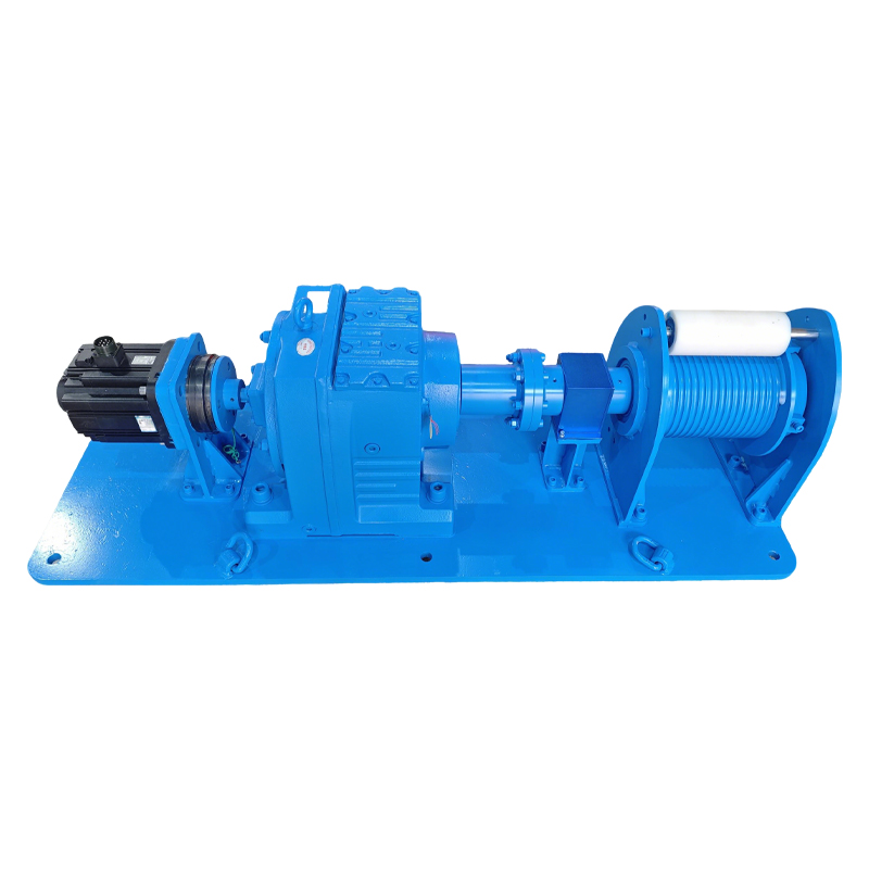
Servo Motor System
Provides responsive motor control for the approved speed and torque envelope.
Control
Programmable PLC Logic
Coordinates operating sequences, motion commands, limit states and machine interlocks.
Measurement
Torque Sensor
Supplies a measurable process signal for load trending, alarms and test-data acquisition.
Transmission
Industrial Reduction Gear
Matches motor output to the required drum torque and line speed; final gearbox type is project-specific.
Mode Selection
Electromagnetic Clutch
Allows controlled separation of drive components for the approved service or operating mode.
Rope Handling
Grooved Dual Drums
Supports guided winding with pressure rollers selected for the rope and duty cycle.
General Technical Range
| Design Item | Available Configuration |
|---|---|
| Nominal Capacity Range | 500 to 8,000 kg; final rating determined by application engineering |
| Electrical Supply | 220–380 V AC with single-phase or three-phase configurations |
| Powered Drive | Servo motor with programmable motion control |
| Gear Reduction | Industrial hardened-gear or planetary arrangement selected for the project |
| Drum Configuration | Dual grooved drums with guided rope winding |
| Load Measurement | Integrated torque sensor with configurable signal range and alarm logic |
| Drive Disconnection | Electromagnetic clutch with project-defined interlocks |
| Control Interfaces | Pendant, HMI, remote commands, PLC interface and data output |
| Base Enclosure Protection | IP55; higher protection available when specified |
| Project Variables | Speed, rope storage, sensor range, feedback devices, data interface, mounting and environmental treatment |
Control and measurement performance must be defined by measurable project requirements. Accuracy depends on sensor selection, calibration, feedback location, rope layers, mechanical compliance, load behavior and commissioning conditions.
3,000 kg Reference Configuration
The following values describe one example system. Final component selection depends on the complete motion and load profile.
| Rated Capacity | Wire Rope Diameter | Drum Speed | Motor Power | Nominal Rope Speed |
|---|---|---|---|---|
| 3,000 kg | 14 mm | 6.3 rpm | 3 kW | 4 m/min |
| Model | Length (A) | Width (B) | Height (C) |
|---|---|---|---|
| 3000KG | 1,922 mm | 600 mm | 462 mm |
Reference Dimensions
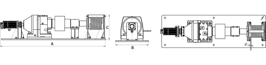
Drawing applies to the reference system. Final dimensions may change with rope capacity, sensor arrangement, gearbox, mounting and controls.
From Torque Signal to Useful Process Data
A torque sensor does not directly guarantee load accuracy or machine safety. Its signal becomes useful only when the measuring range, calibration, mechanical losses, rope geometry and control response are considered as a complete system.
Potential Integration Environments
Research Test Rigs
Apply controlled traction or vertical movement while recording load-related process data.
Aerospace Ground-Test Equipment
Integrate into non-flight test or handling systems after project-specific qualification and compliance review.
Precision Equipment Assembly
Move fixtures or components with configurable speed profiles and monitored transmission load.
Materials and Component Testing
Provide controlled cable force for cyclic, displacement or endurance-test arrangements.
University Engineering Labs
Support advanced experiments involving servo motion, instrumentation and data acquisition.
Special-Purpose Machinery
Add measured pulling or lifting motion to custom equipment with defined control interfaces.
Engineering Options
Qualification Is Application-Specific
Use in aerospace, aviation or other regulated test environments requires project-specific verification against the purchaser’s technical specification and applicable standards. A torque sensor supports monitoring but does not replace independent overload protection, braking, emergency stopping, guarding, structural verification or a complete risk assessment.
Information Needed for a Technical Proposal
Precision-System FAQ
Is this product certified as aerospace-grade?
No universal aerospace qualification is implied by the product name. Compliance must be evaluated against the purchaser’s exact test, documentation, environmental and regulatory requirements.
What positioning accuracy can be supplied?
Accuracy must be engineered and verified for the complete system. Feedback location, rope layers, drum geometry, load dynamics and structural compliance all affect the result.
How accurately does the torque sensor measure line load?
Torque-sensor accuracy alone does not equal line-load accuracy. Gear losses, drum radius, rope layer and calibration method must be included. The required measurement uncertainty should be specified before sensor selection.
Can data be synchronized with our test bench?
Yes, subject to interface definition. Provide the protocol, signal format, sampling rate, timestamps, data channels and required synchronization behavior.
Does torque monitoring replace overload protection?
No. It can contribute to an overload-detection strategy, but independent protective measures and validated safe-stop behavior may still be required by the application.
Instrumented Winch Engineering
Define the Motion, Load Data and Interface
Send LYFOOCRANE your load profile, travel, speed, measurement requirements, test-bench interface and applicable standards. We will review the project and prepare a technically defined servo winch proposal.
Images and reference specifications are provided for preliminary selection. Final performance, measurement uncertainty, dimensions, controls and safety provisions are subject to engineering validation.