

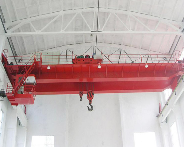
QD Heavy-Duty Double Girder Overhead Crane
The QD double girder overhead crane is designed for demanding industrial lifting applications. Compared with the light-duty LH overhead crane, it features a heavy-duty winch trolley, robust box girders and reinforced end carriages.
Working classes A5, A6, A7 and A8 are available to suit different operating frequencies and load conditions.
It is suitable for workshops, steel plants, shipyards, power plants and other heavy-duty working environments.
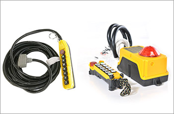
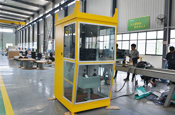
The crane can be operated from an enclosed cabin, providing the operator with a clear view of the working area. Other control options can be configured according to project requirements.
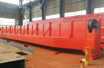
Box Girders
The main girders are fabricated from high-quality steel plate. Internal reinforcement plates create a rigid box-girder structure and provide strong support for the winch trolley.
An integrated service platform provides convenient access to mechanical and electrical components for inspection and maintenance.
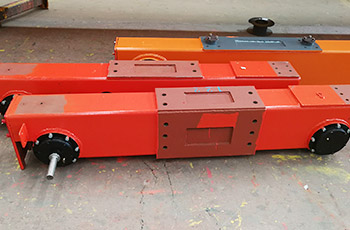
End Carriages
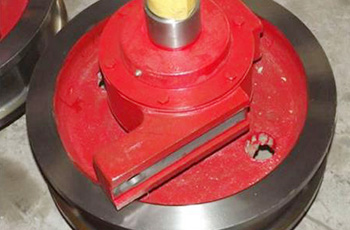
The end-carriage frames are fabricated from rectangular steel sections using automated production equipment. Integrated travel-drive assemblies provide reliable power for smooth crane travel along the runway.
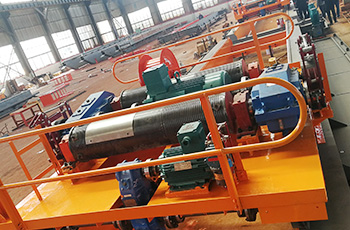
Winch Trolley
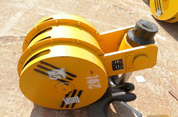
The winch trolley is the core lifting mechanism of the QD crane. Its motor, gearbox, brake, drum, steel frame and wheel assemblies are engineered as an integrated system for heavy-duty service.
Main Components
Frequently Asked Question
What does “heavy duty” mean?
A crane's working class reflects its expected operating intensity. It is determined by factors including the load spectrum, lifting frequency and total operating time. The correct working class should be selected according to the actual application.
Basic Technical Data
The following values are standard reference specifications. Final parameters are confirmed according to lifting capacity, span, lifting height, working class and site conditions.
| Model | QD Type | |||||||||||
|---|---|---|---|---|---|---|---|---|---|---|---|---|
| Lifting Capacity | t | 5 | 10 | 16/3.2 | 20/5 | 32/5 | 50/10 | 75/20 | 100/20 | |||
| Max. Lifting Height | Main Hoist | m | 16 | 16 | 16 | 12 | 16 | 12 | 20 | 22 | ||
| Auxiliary Hoist | m | — | — | 18 | 14 | 18 | 16 | 22 | 22 | |||
| Span | m | 10.5–31.5 | 13.5–31.5 | 13–31 | ||||||||
| Lifting Speed | Main Hoist | A5 | m/min | 11.3 | 8.5 | 7.9 | 7.2 | 7.5 | 5.9 | 6.1 | 3.9 | |
| A6 | 15.6 | 10.4 | 10.7 | 9.8 | 9.5 | 7.8 | 6.1 | 4.9 | ||||
| Auxiliary Hoist | — | — | 14.6 | 15.5 | 15.5 | 10.4 | 7.2 | 7.2 | ||||
| Trolley Traveling Speed | m/min | 37.2 | 43.8 | 44.6 | 44.6 | 42.4 | 38.5 | 38.4 | 33.86 | |||
| Crane Traveling Speed | A5 | m/min | 89.8 (91.8) | 89.8 (91.9, 84.7) | 84.7 (87.6) | 84.7 (87.6) | 87.6 (74.2, 74.6) | 74.6 | 65 | 65.7 | ||
| A6 | 92.7 (93.7) | 92.7 (93.7, 86.5) | 76 (89) | 76 (89) | 89 (75.3) | 75 (76.6) | 66.2 | 65.7 | ||||
| Power Supply | 3-phase, 380 V, 50 Hz or customized | |||||||||||